

Medical Isolated Power Supply and Monitoring System 2019.08
1. Overview
With electronic medical equipment widely used in the field hospital, the threat to patients with leakage current is also growing, especially at those living related sites, patients in the operation or anesthesia, Various electrodes, sensors directly into the human body, small leakage current can lead to death of patients. In addition, some medical equipment for the maintenance of the lives of patients with severe, Once the device is out of power, it will pose a threat to the life of the patient. Therefore, the electrical design for special place of hospital ,It should be strictly used in line with national standards and regulatory requirements for the design of IT systems for power.
ACREL medical IT system insulation monitoring device and fault location system is suitable for hospital operating room, ICU (CCU) and other important places, and can provide a safe place for such continuous, reliable power solutions.
2. Medical Isolated Power Supply Monitoring System
Medical isolation power supply monitoring system is used to centrally monitor the operation of medical IT system in all medical buildings. This centralized monitoring system can be set up in the duty room of hospital electrical operation and maintenance personnel, or integrated in other power monitoring systems. It can be monitored by professional electrical personnel. Once a set of IT system fails, the electrical maintenance personnel can make a judgment in the first time and deal with it according to the situation on the spot.
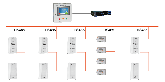
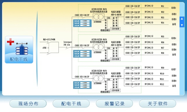
2.1 System Topology
2.2 Software fuctions
ACREL medical isolation power monitoring system is based on touch-screen software design,The software has remote measurement, remote parameter setting and remote self-test and other functions,Software provides a powerful system integrated tools for isolated power centralized monitoring system of all medical group 2 places.The main function of the software are as follows:

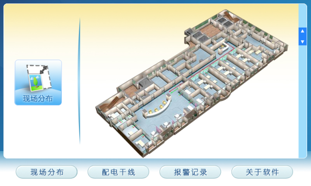
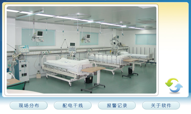
Primary connection diagram and field distribution display
The system has the function of primary connection diagram and field distribution display show,The system can intuitively know and promptly found the alarm location or region of IT power supply system,Allowing professionals to reach the scene in time to troubleshoot.
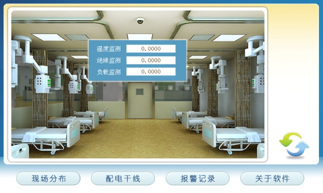
Real-time data acquisition and display
Insulation monitoring meters and insulation fault location meters installed at isolated power system are used to collect the parameters of the isolated power system.Monitoring system interface displays the collected data in real time,These monitoring parameters included IT system insulation resistance, transformer load current , the transformer winding temperature and insulation fault circuit and other parameters;
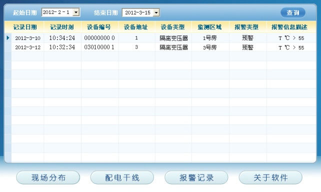
Fault Alarm
The system can process and record all kinds of various medical isolated power system fault occurs,Such as insulation fault, overload fault, over temperature fault and wiring disconnection fault and other fault,And it can display fault type, monitoring values, and fault location and failure time and other information on the display screen.And it starts the audible and light alarm of the monitoring system,It is timely to remind the relevant personnel to troubleshoot.Among them, the audible alarm signal can be manually removed.
Remote parameter setting and inquiry
Through the system, Professionals can remotely adjust and set up all kinds of alarm parameters threshold of insulation monitors in each medical isolated power system according to the requirements, Professionals can also view any parameter values for these alarms. Parameters include insulation alarm values, the load current alarm values and isolation transformer temperature alarm values, etc.
Graphic display
The system can display the insulation status, load status of each set of isolated power systems in graph form.The system can also display isolation transformer temperature conditions and their trends in graph form. System can help managers understand and analyze operational changes in each power system, so maintenance personnel can maintain and repair some of the targeted system.
2.3 Medical Isolated Power Supply Monitor
Application Environment
—Operating temperature:-10℃~+55℃
—Storage temperature:-20℃~+70℃
—Relative humidity:≤ 95% No condensation
—Altitude:≤2500m
—Pollution Level:Level Ⅲ
—Installation category:Level Ⅲ
The main components
The following table lists the ACREL medical isolation power monitor cabinet main functions and components:
Cabinet Name Parameters | Medical Isolation Power Supply Monitor Cabinet | |
Dimensions | 500(H)×400(W)×190(D) | |
main components | Computer | 10’’ TFT Color touch screen |
I/O modules | I/O Built-in remote intelligent I/O modules | |
Power Modules | Switching Power Supply | |
Lights | Red(warning)Yellow(Early Warning)Green(normal) | |
Entity structure diagram
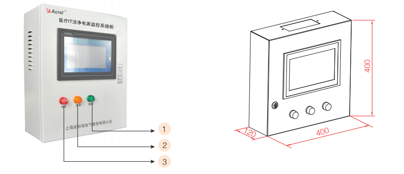
1.Operation indicator (green), the indicator light indicates the system is operating normally.
2.Communication fault indicator (yellow), lights indicate the system receives the warning signal.
3.Alarm indicator (red),light indicator that monitoring system receives the alarm signal.